Saltar al contenido Skip to content
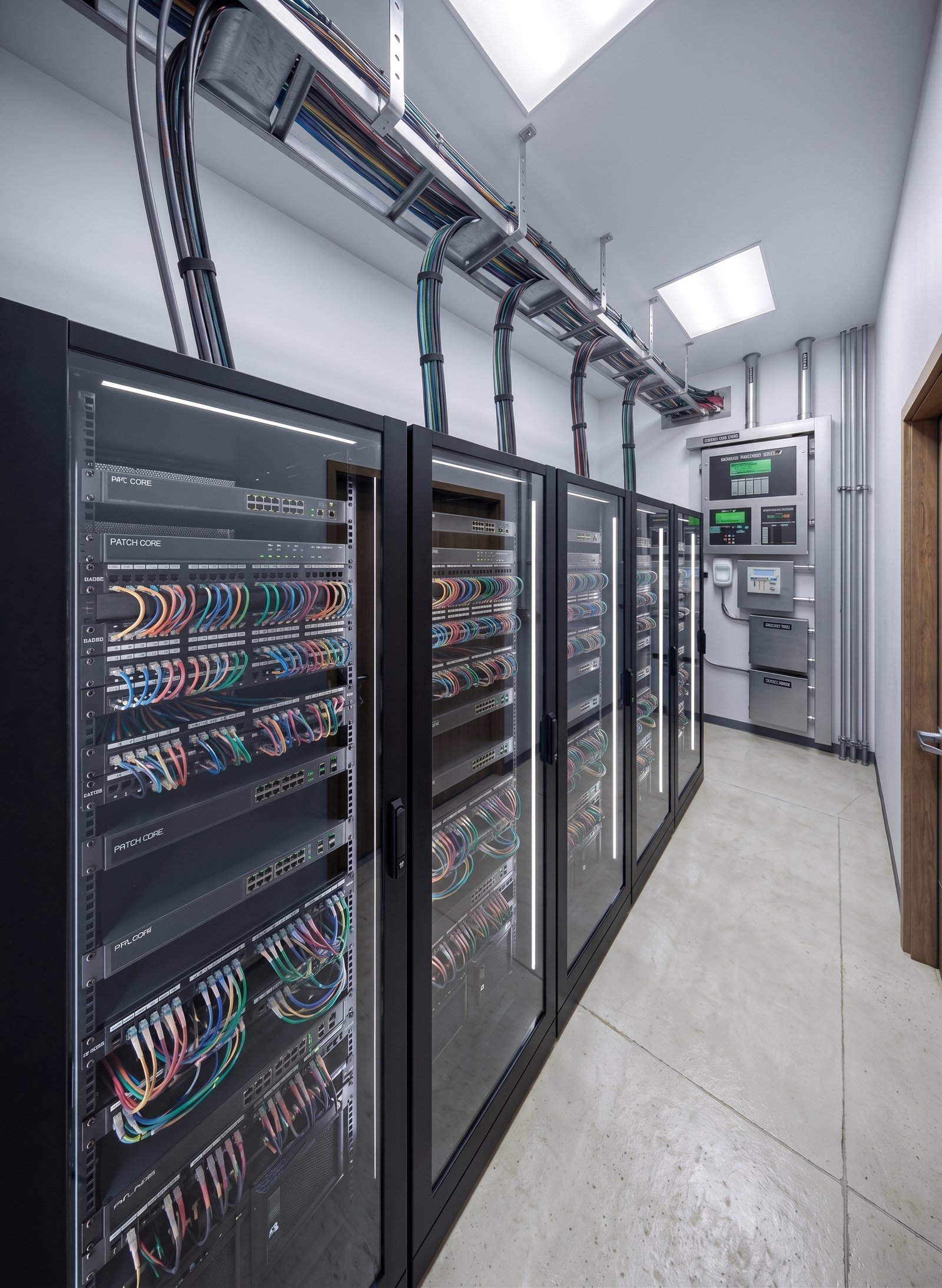
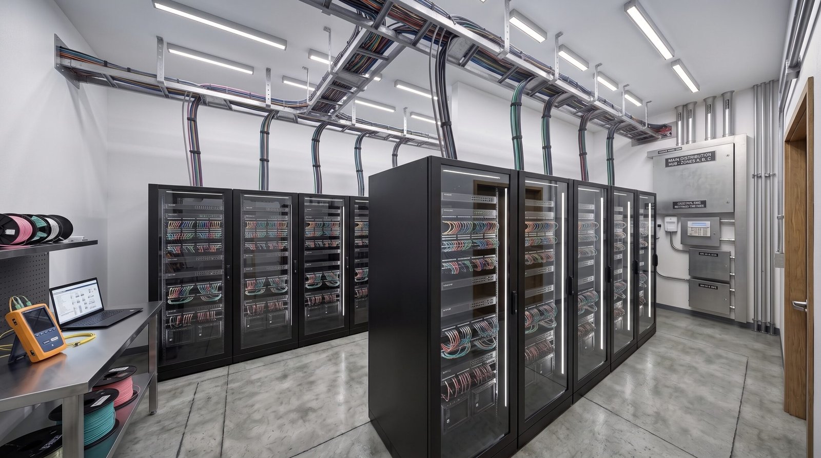
Server room with rows of glass-door network cabinets, color-coded overhead cable tray, and a testing station in the foreground — Data Center and Server Room Modeling
All projects

07 / 07 · Data center modeling

Data Center and Server Room Modeling

BIM modeling and technical coordination for the highest-density installation point in the project, resolving clashes digitally before installation.

Project profile

Location Pending
Sector Technical infrastructure / data center
Coordination MEP + Architecture
Methodology 3D BIM modeling

01 Results

Financial impact and avoided cost overruns

5 Fire-sealed cable pass-through points, defined before the slab was poured.

We are also tracking: clashes detected and resolved in the model before construction, RFIs and on-site rework during installation, free rack U for future growth, and deviation between the model and as-built conditions. The estimated savings or avoided cost overrun figure will be defined at project closeout.

02 The challenge

The Project Challenge

The technical room is the highest-density installation point per square meter in the entire project: cable tray, piping, sprinklers, light fixtures, and detection all compete for the same plenum, and cable pass-through points have to be defined before the slab is poured or it has to be broken open afterward.

The challenge was to resolve those clashes digitally, fix the position and diameter of every pass-through point with its fire seal before pouring, guarantee real bend radii at the cable entry into the racks, and validate operation and maintenance clearances (door swing, front aisle, equipment removal).

03 The solution

The Cabo Solution

We modeled and coordinated the data center and server room in a single digital prototype:

01
Rack and Cabinet Layout Coordinated placement with real operation and maintenance clearances.
02
Cable Routing and Conduit Main cable tray and galvanized conduit for service entries with no improvised crossings.
03
Cable Pass-Through Points and Fire Seals Position and diameter of every pass-through point defined and validated before pouring the slab.
04
Lighting and Detection Room lighting and the fire detection and alarm panel integrated into the model.

04 Technical media

Technical Media Module

Fig. 01  ·  3D walkthrough

Project gallery

01 / 05
Server room — general view — Data Center and Server Room Modeling
Server room — general view
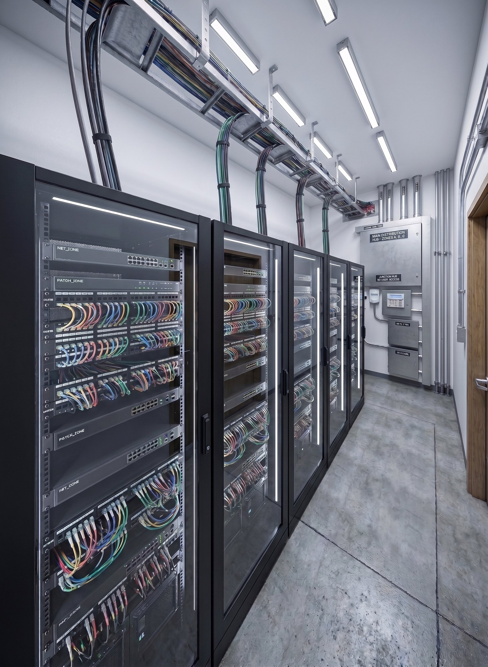
Rack corridor — alternate view — Data Center and Server Room Modeling
Rack corridor — alternate view
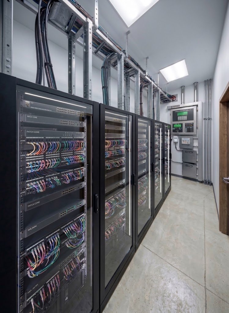
Cable pass-through points — fire seals — Data Center and Server Room Modeling
Cable pass-through points — fire seals
Additional walkthrough of the data center
Commissioning bench — network certification and testing — Data Center and Server Room Modeling
Commissioning bench — network certification and testing

05 Delivery

Delivered Results

Coordinated Model Data center and server room with clashes resolved before construction.
Technical Installation Documentation Plans, sections, cable-tray elevations, and pass-through breakdowns.
Validated Pass-Through Points Position and fire seal of every pass-through point defined before pouring the slab.

Next step

Does your project have high-density technical installations?

We resolve clashes digitally before they ever reach the job site.